Can simulation replace testing for robustness, reliability and safety?
How can simulation replace massive testing and manual safety analysis?
Verifying an electronic circuit conventionally takes massive testing plus manual safety verification against the IEC and ISO standards. A safety and reliability simulation detects hidden design errors before the first prototype is built, which is where the reduction in design cycles comes from.
To verify the quality and reliability of electronic circuits, massive testing is required. Furthermore, manual safety verification is needed in order to comply with various IEC/ISO standards. BQR introduces a new type of safety and reliability simulation (instead of massive testing and manual analysis) which detects hidden design errors before manufacturing the first prototype for testing. The simulation reduces design cycles thereby saving money and reducing TTM. The product becomes best in class, free of hidden design errors, and improves the manufacturer's reputation. Circuit simulator for design error detectionBQR offers software and professional service for component stress analysis by circuit stress simulation. The simulation includes several layers to cover all potential failure types, as follows: Automated calculations of electrical operational parameters such as Voltage and Current for each IC Pin, Net, and Pad. Performing a component derating analysis and providing electrical constraints for the next step Automated design and schematic analysis which tests all ICs and semiconductors and compares the previous electrical constraints to components’ datasheets requirements Provide full electrical stress analysis and derating to avoid over-stress and over-design Help to select the optimal components size/rating for the operational temperature Calculate the MTBF and provide accurate electrical stress data for Life (Probability of failures vs. time) and Physics of Failure- PoF Automated components failure modes and safety analysis (FMEA/FMECA/FTA) The analysis includes electronic hardware and software failures Guide the final verification test plan Automatically generate all IEC/ISO standards reports for the authorities Reports at the component, board, and system levels in early design stages
What makes this simulation different?
It runs inside the ECAD tools already in use — Altium, OrCAD and Mentor — with all simulation data embedded in the schematic database, so a design change is re-simulated rather than re-entered, and library data is reusable across projects.
The new simulation is integrated with major E-CAD tools such as Altium, OrCAD, and Mentor All data related to the simulation is embedded in the schematic database, so if there is a design change it can be done easily Data is organized in libraries for easy reuse.
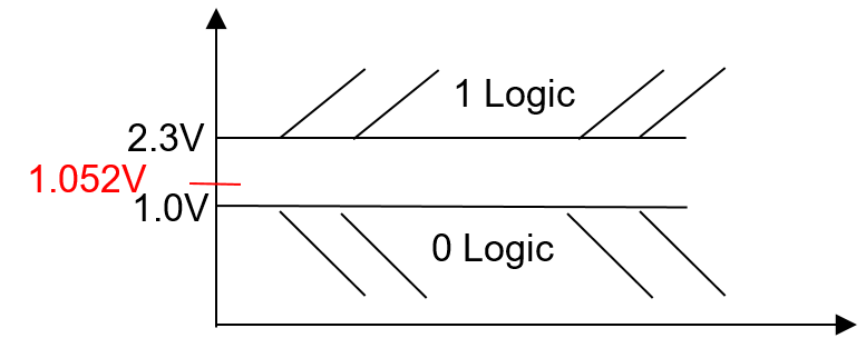
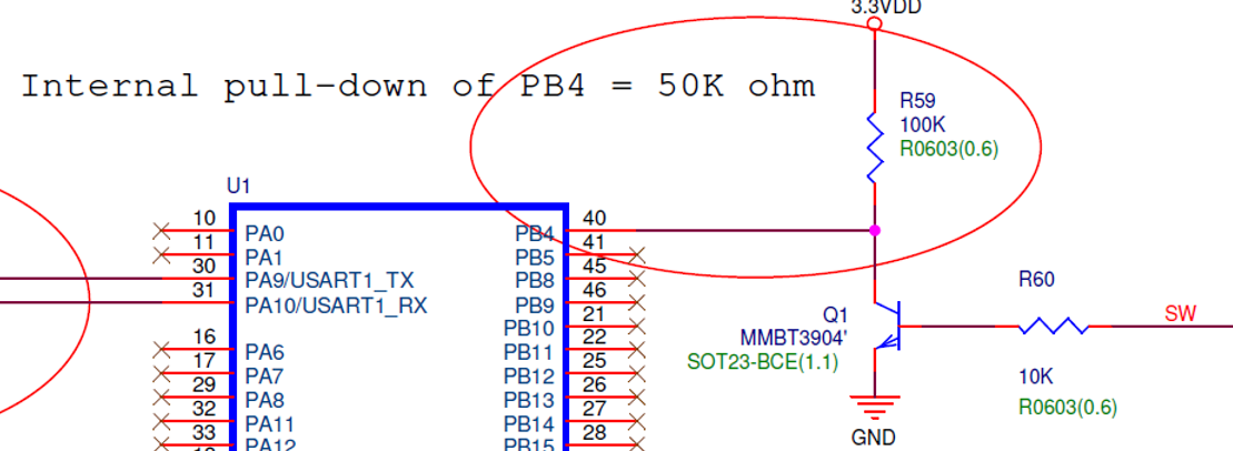
Following is an example design error that was identified using BQR’s simulation software: In the figure below transistor Q1 provides digital input to pin 40 of U1. It should be above 2.3V for “1” logic, and below 1.0V for “0” logic. But Q1 provides 1.052V which U1 will intermittently interpret as “1” or “0”.This design error results in unstable U1 functionality which is difficult to detect and isolate.