MTBF (Mean Time Between Failure) is an important parameter for various analyses:
- Reliability / Availability Analysis – Probability of mission failure or system downtime
- Safety – Occurrence probability of a safety event
- Spare Parts Provisioning – Required spare parts to ensure system availability
- Warranty – Probability of failure before warranty expires
The mean number of failures is used for these analyses.
Tenders for utilities, defense, aerospace, rail, and telecom systems often include an MTBF requirement that designers must meet.
Initially, the designer allocates failure rates to subsystem assemblies. When a detailed design is available, a more accurate MTBF calculation must be conducted to verify compliance with the requirement. Finally, during field testing, an MTBF demonstration takes place by accumulating field failure data.
How is MTBF calculated?
With field failure data, divide total operating hours by the total number of failures — valid only under comparable operating conditions, and expressible to a chosen confidence level. Without field data you use a prediction method, calculated from the bottom of the product breakdown tree upwards.
If you have field failure data, divide the total operation hours by the total number of failures to obtain the field MTBF. You can also calculate field MTBF to specific confidence levels.
Note: This MTBF is only valid under similar operating conditions. If you do not have field data, MTBF prediction methods must be used.
MTBF is usually calculated from the bottom to the top of a product/system breakdown tree. The calculation steps are as follows:
- Calculate the MTBF of “end items” at the bottom of the breakdown tree.
- Use the lower-level MTBF to calculate the MTBF at the next higher level.
- Repeat the process until the entire tree is calculated.
“End item” MTBF can be obtained from various sources:
- Statistical analysis of field failure data
- Standard prediction methods (MIL HDBK 217, Telcordia 3, SN29500, FIDES, etc.)
- OEM datasheets
- Failure databases such as NPRD and OREDA
Note: The equipment MTBF value represents the expected rate of failure under specific operating profiles and environmental conditions. Conversion factors may be required to adapt the MTBF value for different conditions.
Prediction methods typically provide “end item” MTBF according to the following formula:
MTBF = 1 / (λ₀ · ΠS · ΠD · ΠE · ΠT)
| Parameter | Meaning |
|---|---|
| λ₀ | Item base failure rate |
| ΠS | Stress factor (e.g., ratio of actual power applied to a resistor vs. rated power) |
| ΠD | Duty Cycle |
| ΠE | Environment factor (e.g., ground, mobile, naval, airborne, space) |
| ΠT | Temperature factor, usually in the form of an Arrhenius equation accounting for activation energy |
Additional Π factors in prediction methods account for manufacturing and screening quality, electronic component packaging, humidity, and more.
Higher-level MTBF is calculated as a function of the lower-level item’s MTBF:
MTBF_parent = 1 / ∑ᵢ(1 / MTBFᵢ)
Where MTBFᵢ is the MTBF of the i-th direct child. This equation accounts for the failure of any child item, which is beneficial for:
- Worst-case assumptions
- Serial reliability models
- Maintenance calculations
If you wish to account for redundancies, you need to calculate MTBCF (Mean Time Between Critical Failures). A Reliability Block Diagram (RBD) can be used for MTBCF analysis.
What are the two ways to calculate MTBF under MIL-HDBK-217F2?
Parts Count assumes default values of ΠS = ΠT = ΠD = 1; Parts Stress accounts for all three. The difference between them is whether the calculation uses the real stress on each component or a placeholder.
Specific base failure rates and factors are defined in prediction standards. There are two methods for calculating MTBF of electronic products according to MIL HDBK 217 F2:
- Parts Count – Assuming default values of ΠS = ΠT = ΠD = 1
- Parts Stress – Accounting for ΠS, ΠT, and ΠD
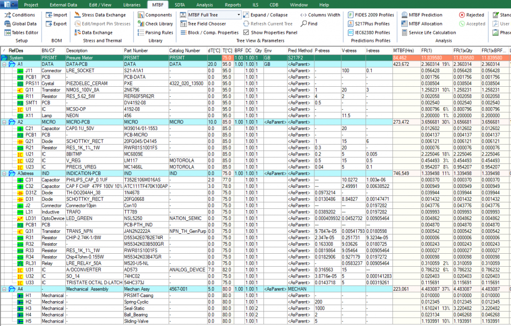
Parts count can be calculated using BQR’s online application: BQR-Digital.
Additionally, parts count can be calculated using BQR’s ECAD Plug-In and fiXtress desktop software.
How do you improve a calculated MTBF?
Move from the parts-count method to parts-stress: it requires you to supply component stresses, but that is also where the engineering value is, because an over-stressed component shows up as a very low MTBF instead of hiding behind a default.
If you calculated MTBF using the parts count method, you might obtain a better MTBF value by using the parts-stress method. While this requires inputting component stresses, actual engineering value can be derived from such analysis. For example, an over-stressed component will exhibit a very low MTBF. By examining a Pareto view of the failure contributors, you can identify over-stressed components.
Better yet, conduct a component derating analysis and then utilize the data for MTBF prediction. BQR’s fiXtress Pro provides an easy platform for conducting component derating and MTBF prediction.
What are your MTBF calculation needs? Contact us for additional details regarding BQR’s MTBF prediction software and services.