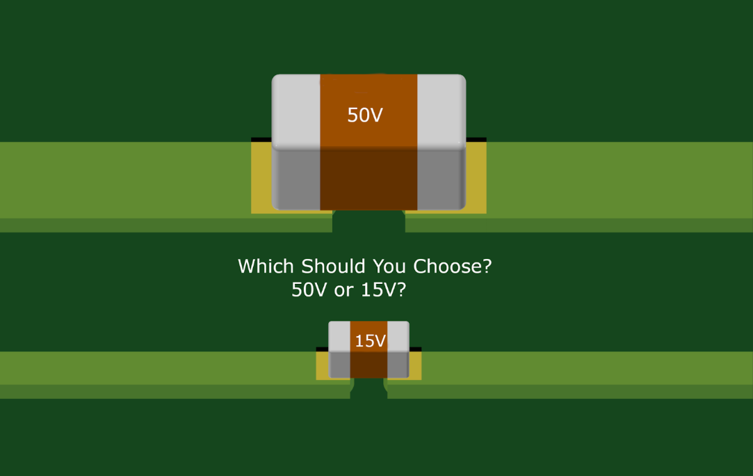
Why is component selection the critical decision?
Components are the building blocks of an electronic system, so their performance sets the reliability and functionality of the finished product — and derating, using them below their maximum ratings, is how that choice gets made deliberately rather than by habit.
An engineer's most critical decision is selecting the right component during PCB design. Components form the building blocks of any electronic system, and their performance can significantly impact the overall reliability and functionality of the final product. But how can you ensure your chosen components are suitable and optimized for long-term performance? The answer lies in derating components—ensuring components operate well below their maximum capacity, reducing stress, and increasing reliability. In this blog, we’ll explore what derating is, why it matters, the challenges of manual derating, and how automated tools can simplify the process.
What is component derating?
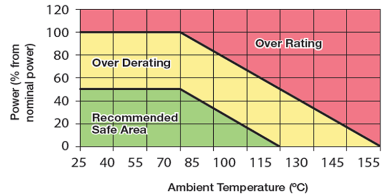
Derating means operating a component well below its maximum rated voltage, current and temperature — a resistor rated for 2 watts used at 1 watt — for the same reason you would not run a car engine permanently at maximum RPM.
Imagine driving a car engine constantly at its maximum RPM. While it might work in the short term, the long-term damage would be inevitable. Similarly, electronic components have maximum voltage, current, and temperature ratings, among other parameters. Derating involves using components at levels significantly below these maximum ratings. For instance, a resistor rated for 2 watts might be used at only 1 Watts in your design. This ensures that the component is not pushed to its limits, which can cause failure due to overheating, electrical overstress, or wear over time.
Derating is not merely a recommendation; it is necessary in high-reliability industries, such as aerospace, medical devices, and automotive. It’s also a best practice in consumer electronics to extend product lifespans and minimize warranty claims.

Why does derating matter?
Derating buys reliability, but getting it right takes precise calculation and an understanding of each component and the environment it operates in — which is why it is so often approximated.
Derating provides multiple benefits:
- Increased Reliability: Operating components within safe margins reduces the likelihood of failure and increases the lifespan of components, ensuring consistent performance over time.
- Thermal Management: Components operating below their capacity simplify thermal design by mitigating issues caused by component overheating.
- Enhanced Safety: For critical applications, derating ensures that components can handle unexpected surges or environmental changes without failing.
However, achieving optimal derating requires precise calculations and a deep understanding of the components and their operating environment.
Why doesn't manual derating scale?
Manual derating means evaluating the stress on every component under worst-case conditions. That is practical on a simple design and impractical on a modern one with hundreds or thousands of components and multi-board interconnects.
Traditional derating is often done manually, requiring engineers to evaluate the stress on each component under worst-case conditions. While this approach can be practical for simple designs, it quickly becomes impractical for modern PCB designs that may involve hundreds or thousands of components and multi-board interconnects. Key challenges include:
- Time-Consuming Process: Analyzing each component is labor-intensive and slows the design process.
- Error-Prone: Human errors in calculations or oversight of critical components can lead to reliability issues.
- Limited Scalability: Manual derating becomes increasingly unmanageable as designs grow in complexity.
How do automated tools simplify derating?
They integrate directly into the design environment, so the derating runs against the live design and returns actionable results in place of a separate report produced after the fact.
This is where advanced reliability engineering tools like BQR’s Synthelyzer™ ECAD Plugin and fiXtress® come into play. These tools integrate directly into your design environment, automating the derating process and providing real-time actionable insights.
- Automate Manual Process: Greatly reduce the manual effort to verify your design during your circuit definition.
- Real-Time Analysis: Evaluate components dynamically during the design process, saving time and ensuring thorough analysis.
- Accurate Stress Evaluation: They calculate electrical and thermal stresses using real-world operating conditions, ensuring precise derating.
- Early Detection of Overstress: Potential issues are flagged early in the design cycle, allowing for proactive adjustments before costly revisions are needed.
How does derating fit into the Shift-Left approach?
Shift-Left means addressing problems early rather than at late-stage testing or prototyping, and automated derating is what lets reliability be built into the design from the outset instead of confirmed at the end.
The Shift-Left design philosophy emphasizes addressing potential issues early in the design process rather than during late-stage testing or prototyping. Automated derating analysis aligns perfectly with this approach by ensuring reliability considerations are baked into the design from the outset.
For example, using tools like Synthelyzer™, engineers can:
- Select components optimized for their specific design constraints.
- Avoid overstressed components that could lead to failures in the field.
- Integrate derating analysis seamlessly into their existing workflows.
When is derating analysis mandatory?
In aerospace and defence, component derating analysis is frequently a contractual deliverable named in the tender itself. Medical devices and other regulated industries require safety analysis, whose failure-rate calculations depend on the operational stresses.
In some cases, component derating analysis is mandatory. For example, in aerospace and defense industries, tenders for systems often require component derating analysis as part of the contractual deliverable documents. Additionally, medical devices and other industries require safety analysis. The analysis must include failure rate calculations that rely on operational stresses.
Consider a design team working on a new medical device. If they manually derate critical components like capacitors and resistors using traditional methods, they potentially miss less obvious but equally important components. By integrating automated derating tools like Synthelyzer™ into their workflow, the team can automate stress analysis for all components, catching potential issues that might have been overlooked. The result? A more reliable product, faster time to market, and reduced development costs that meet stringent requirements across industries. Learn more about Design for Reliability.
Is automated derating necessary, or just good practice?
For a modern PCB it is necessary rather than optional: manual methods can cover a simple design, but comprehensive and accurate derating across a modern board needs automation.
Component derating is not just a best practice but a necessity for designing reliable and long-lasting electronic systems. While manual methods may suffice for simple designs, modern PCBs require automated tools to ensure comprehensive and accurate derating analysis. Tools like BQR’s Synthelyzer™ and fiXtress® empower engineers to integrate derating into their designs effortlessly, improving reliability while reducing time-to-market.
Derating is your first step toward robust PCB designs, but it’s only part of the equation. In the next blog, we’ll explore how schematic reviews play a critical role in detecting errors before design layout.
Connect with us to learn how we can help you improve product reliability and reduce time to market.