How confident can you be that a board design is actually robust?
Functional specification, design, simulation and testing all confirm that a board does what it should — none of them confirms that it will keep doing it under real stress, which is the gap Design for Reliability addresses.
As an engineer, you spend most of your time working on electronic board development, which includes functional specifications, design, simulations, and testing of the product.How confident are you that your product is robust and reliable? Have you taken all the necessary steps to ensure that design errors are detected and that your customers will not experience failures?
Of course, you believe you’ve done everything to ensure the product’s reliability, yet the reality may be different.
What does it cost to find these defects late?
Defects found in internal testing cost repeated cycles of root cause analysis, corrective action and verification — unplanned development cost, programme delay and missed market windows. Found by the customer instead, they cost warranty and reputation.
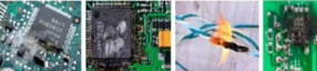
These defects are often discovered during internal testing, leading to multiple cycles of root cause analysis, corrective actions, and verification. This process can result in unexpected development costs, program delays, and missed market opportunities. Worse still, product defects found by your customers can lead to significant warranty costs and damage to your company’s reputation.
What are the steps of the DFR model?
The DFR model is built in layers, each removing a class of error before the next begins, starting with schematic stress simulation to eliminate electrical and stress errors at the schematic stage.
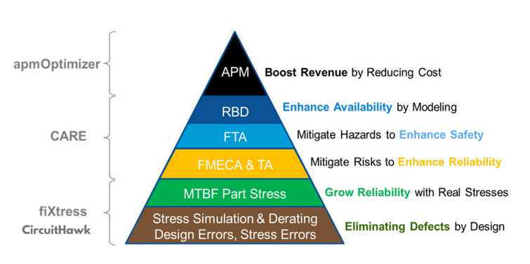
The solution to eliminating design errors is illustrated by the BQR fiXtress DFR Model, which begins with a solid foundation. The DFR Model is built layer by layer to support robust, bug-free electrical circuits.
Step 1: Schematic Stress Simulation The first step aims to eliminate electrical and stress errors during the schematic design stage. The BQR software suite was primarily developed to simulate component stresses (i.e., P, V, I, Tj). It conducts Stress & Derating Analysis on circuit schematics of any size (from hundreds of pads to tens of thousands) and any type of electrical circuit (e.g., Analog, Digital, RF, or Power), all before layout and production. This approach offers high flexibility for improving designs at a lower cost compared to fixing product defects after the First Article Tests.
Step 2: MTBF Part Stress The second step uses the simulated stresses to calculate the reliability of the electrical circuit with more accurate and realistic MTBF (Mean Time Between Failures) predictions. This enables the identification of the weakest links in the design that could lead to poor performance and high failure rates.
Step 3: FMECA & TA The third step enhances electrical circuit reliability by predicting critical failure modes, which can help mitigate technical risks discovered through FMECA (Failure Modes, Effects, and Criticality Analysis). This is followed by Testability Analysis (TA), which ensures effective defect detection coverage and helps isolate defects.
Step 4: FTA The fourth step addresses safety hazards, a requirement for industries such as Defense, Aerospace, Automotive, and other critical sectors. This step brings the design to the next level by enhancing availability through Reliability Block Diagram (RBD) modeling for redundancy and boosting revenue using APM (Asset Performance Management) to reduce costs from operating and maintenance optimization.
Why does it matter that the tools share one database?
A shared core database lets simulation results be reused across analyses, so a design change updates every dependent simulation and result at once instead of invalidating work nobody has re-run yet.
The BQR DFR tools can be used individually and self-contained, but they can also operate through a common core database that enables seamless interaction between tools. This allows for the reuse of simulation results across multiple analyses, improving accuracy and saving significant time. It provides an efficient way to ensure that design modifications are updated instantly across all simulations and analysis results.
Connect with us to learn how we can help you improve product reliability and reduce time to market.